IP Routing and Subnets
This article describes the basics of IP routing. We will consider the example of a simple network and trace the life of a packet as it gets routed from one node to another. The routing tables at each node will be discussed.
Before we go into depth of IP routing, we need to understand IP addresses. This is covered in the next section.
IP Address Classification
IP addresses are 32 bit integers which are represented in the familiar dot based notation. The dot based notation is nothing but a decimal representation for each byte of the IP address. For example, an IP address with a hex value of 0x800A080B is represented as 128.10.8.11.
The internet, as the name suggests, is a network of networks. Thus to uniquely identify a host on the internet, one needs to know the network's id and the host's id in the network. Thus IP address consist of two components, the network id and the host id. The network id is the number assigned to a network in the internet. Host id represents the id assigned to a host in the network.
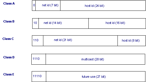
The figure below shows different classes of IP addresses. These addresses differ in the number of bits assigned to the network and host ids. Different classes of addresses serve different needs. For example, a class A IP address is suitable when the internet consists of a small number of networks but each network consists of a large number of hosts. On the other extreme, class C addressing is suitable for internets with a very large number of networks, with a small number of hosts per network.

An Example Internet
Subnets
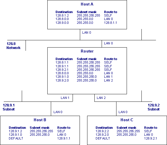
The figure below describes a small internet consisting of three networks 128.8, 128.9.1 and 128.9.2. Strictly speaking, the internet consists of 128.8 network and 128.9.1 and 128.9.2 sub-networks (subnets). As we have seen in the previous section, 128.8 and 128.9 should have been classified as the network portion of a class B IP address. In this network 128.9 has been divided into two sub-networks (128.9.1 and 128.9.2) by using one of the bytes of the two byte host id as sub-network id.
Another way to look at this is that the first three bytes of IP addresses in 128.9.1 and 128.9.2 subnets are used for routing the packet. The other bits in the IP address are don't care from routing point of view. The specification of bits that should be used for routing is specified by associating a subnet mask with a routing entry. In this example, the subnet mask is 255.255.255.0 (0xFFFFFF00).
IP Routing
Networks in the internet are connected to each other via routers. Routers carry traffic from one network/subnet to another. Routers maintain a routing table to decide how to route the IP packets. Each routing entry consists of the destination address, subnet mask and "route to" field. When a message needs to be routed to an IP address, the following steps are followed:
- The destination IP address is masked with the subnet mask and then compared with the destination field for all entries in the routing table.
- This comparison may yield a match with more than one entry the entry with the longest subnet mask will be selected. E.g. , a packet destined for 128.8.1.2 reaching Host A would match the entries corresponding to 128.8.1.2 and 128.8.0. The entry corresponding to 128.8.1.2 will be selected, as it has a longer subnet mask.
- Once an entry has been selected, the "route to" field is
consulted and the action taken depends on the contents of this field:
- If the "route to" field contains SELF the packet is meant for this node. The IP packet is passed to the OS for application processing
- If the "route to" field contains a LAN interface id, the packet is destined for a LAN that is directly connected to the router/host. In this case, the packet is routed directly on the LAN.
- If the "route to" field contains an IP address, the packet is forwarded to the IP address specified. Further routing of the packet will be carried out by the specified IP address.
Note: IP routing also supports a default entry. If the packet does not match any other entry, it is routed according to the default entry.

Multiple IP Addresses
Another important aspect of internets is a node in the internet can have multiple IP addresses. There will be one IP address per interface. For example, the Router in the figure above has three IP addresses, viz. 128.8.1.1, 128.9.1.1 and 128.9.2.1.
Routing of a Packet from Host A to Host C
Here we will trace the path taken by an IP packet sent from Host A to Host C. Routing related fields in the Ethernet MAC header and IP header are shown.
Host A originates an IP packet towards Host C
- Application sends a message to Host C by sending it to 128.9.2.2 IP address (Host C's IP address).
- This IP address matches the entry corresponding to 128.9.0.0. The "route to" field for the selected entry contains another IP address - 128.8.1.1. This is the IP address of the Router.
- The IP routing table is accessed again for 128.8.1.1.
- The entry that matches 128.8.1.1 contains LAN 0 interface id. This specifies that the destination node is directly connected to the host.
- This packet is passed to the device driver.
- Device driver consults the ARP cache to identify the Ethernet MAC address corresponding to the 128.8.1.1. (ARP is covered in another article).
- Ethernet frame is sent to the MAC address found by ARP.
The packet sent on the 128.8 LAN is:
| Ethernet MAC Header | IP Packet Payload | |||
| Destination MAC Address | Source MAC Address | Destination IP Address | Source IP Address | Payload |
| Router MAC Address | Host A MAC Address | 128.9.2.2 | 128.8.1.2 | |
Router send the IP packet to Host C
- Router receives the Ethernet frame and passes it to the IP layer.
- IP routing table is consulted and a matching entry is found corresponding to 128.9.2 subnet.
- Packet is routed on the LAN 2 interface.
- Host C's MAC address is found from the ARP cache.
- Ethernet frame is addressed to Host C MAC Address.
The packet sent over the 128.9.2 LAN is:
| Ethernet MAC Header | IP Packet Payload | |||
| Destination MAC Address | Source MAC Address | Destination IP Address | Source IP Address | Payload |
| Host C MAC Address | Router MAC Address | 128.9.2.2 | 128.8.1.2 | |
Host C receives the IP packet
- Host C receives the Ethernet frame and passes it to the IP layer.
- IP routing table is searched and a match is detected with 128.9.2.2 entry.
- The "route to" field contains SELF, so the message is passed to the higher layer for delivery to the application.