Synchronizer Design Pattern for Frame Synchronization
Intent
Many systems used in digital communication send data in synchronous back-to-back frames. When a receiver tunes to such a data stream, it has no knowledge of the frame boundaries. The Synchronizer Design Pattern is used to look at the raw incoming bit or byte stream and detect and align to the frame structure. The frame structure is detected by searching for a sync pattern in the frame.
Once the synchronization is achieved, the Synchronizer confirms the presence of the sync pattern in every frame. If the sync pattern in missed a certain number of times, loss of sync is declared.
Also Known As
- Sync Handler
- Frame Synchronizer
Motivation
On many occasions there is need to maintain synchronization between two entities connected at opposite ends of a link. This design pattern provides mechanisms for:
- Achieving initial synchronization (sync)
- Once sync is achieved, confirming the presence of the sync framing
- Initiating loss of sync procedures
Applicability
This pattern can be used in the following cases:
- Maintaining sync in digital communication systems. e.g. digital trunk synchronization procedures. This design pattern provides a broad framework for implementing such sync systems.
- The design pattern can also be applied in more general scenarios where periodic message communication is involved between entities to exchange state information. A good example would be routing protocols where periodic routing updates are used to keep different routers in sync with each other.
Structure
The Synchronizer is implemented as a hierarchical state machine. The following states are defined for the state machine:
- Un-synchronized and searching for sync
- Un-synchronized but confirming sync
- Synchronized and in sync
- Synchronized but confirming sync loss
Each state is represented with a class.
Participants
Synchronizer state machine class is the key participant in this pattern. The state machine uses state classes to keep track of state.
Collaboration
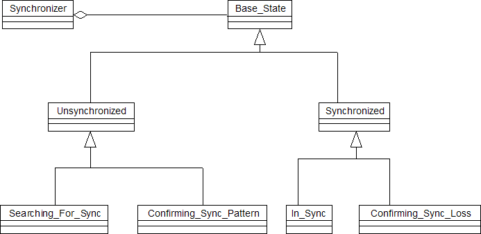
The following diagram shows the relationship between various classes involved in the Synchronizer design pattern:

It is clear from the figure above that the state machine is organized into two high-level states, synchronized and un-synchronized. These states act as the base class for the following sub-states:
| High level state | Sub-state | Description |
| Un-synchronized | Searching_For_Sync | The Synchronizer starts in this state. In this state, the Synchronizer is hunting for the sync pattern in the periodic data. In many cases, the framing of the data is not known, so the search for sync pattern is carried out bit by bit. The Synchronizer transitions to the Confirming_Sync_Pattern state after the first sync pattern is detected. |
| Confirming_Sync_Pattern | Once the first sync pattern is detected, the sync pattern needs to be confirmed. If the sync pattern is detected with the expected periodicity, the Synchronizer transitions to In_Sync state. If the sync pattern is not detected with expected periodicity, the Synchronizer transitions back to the Searching_For_Sync state. (This might happen due to a false detection of the sync pattern) | |
| Synchronized | In_Sync | The system transitions to the In_Sync state after the sync pattern has been detected and confirmed. When in this state, the Synchronizer checks for every expected sync pattern. If the expected sync pattern is not detected, a sync loss might have taken place. Sync loss detection and confirmation is handled in the Confirming_Sync_Loss state. |
| Confirming_Sync_Loss | The Synchronizer enters this state even when one sync pattern is missed. The main objective here is to decide if the sync pattern loss was an isolated event or it points to link failure (sync loss). When in this state, the synchronizer checks for a pre-defined number of sync patterns. If all the expected sync patterns are missing, the system transitions to the Searching_For_Sync state. If sync patterns loss is not permanent, the system moves back to In_Sync state. |
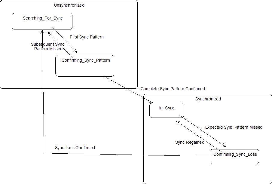
The figure below is the state transition diagram for the synchronizer.

Consequences
Use of this pattern has the following benefits:
- Provides a common framework for implementing synchronization logic
- Use of hierarchical state machine reduces the amount of code by reducing code duplication in various states.
- Use of a state machine forces the developer to handle all possible cases of synchronization events.
Implementation
The implementation is explained in terms of the following scenarios:
Attaining Synchronization
- System starts up in "Searching For Sync" state. In this state, the incoming data stream is being analyzed bit by bit, looking for the occurrence of the sync pattern.
- As a soon as a first sync pattern is detected, the system transitions to the "Confirming Sync Pattern" state.
- Now the system checks if the sync pattern is repeating as expected. This check is made according to the specified periodicity.
- If the sync pattern is repeating, the system transitions to the "In Sync" state. (If the sync pattern was not found, the system would have transitioned back to the "Searching For Sync" state)
- At this point, the system is considered to be synchronized.
Loosing Synchronization
- When the system is synchronized, it is in the "In Sync" state. In this state, the system is constantly monitoring the periodic occurrence of the sync pattern.
- If an expected sync pattern is found to be missing, the system transitions to the "Confirming Sync Loss". The system is still in a synchronized state. The main purpose of the "Confirming Sync Loss" state is to check if the loss of sync was an isolated event or it represents complete loss of sync.
- In the "Confirming Sync Loss" state, the system looks for the sync pattern at the expected time interval. If the sync pattern is seen again, the system transitions back to the "In Sync" state.
- In this case, the sync pattern is not detected for a pre-configured number of times.
- The system is now in sync loss state. The system is transitioned to the "Searching For Sync" state.
Sample Code and Usage
The following code defines a simple byte level synchronizer. Here the synchronizer is receives one byte at a time from the serial link.
Synchronizer.h
Synchronizer.cpp
Known Uses
- Digital Trunk Synchronization
- Frame and Super-frame synchronization in TDMA and CDMA systems